


Источник: Inside an "X" Head / Repairing the Most Powerful Head Elinchrom Ever Made.
"Что бы я ни делал, пилотная лампа, только что полученной головки Elinchrom X, не работает... "
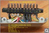
Распайка разъёма (20 штырьков, DIN 41622) ведущей лампы:Hermes писал(а):Just received my second Elinchrom X head to find that its modelling lamp would not work no matter what I tried.
I got a good deal on it and the flash centre charge a fortune to work on these high-powered heads so I thought I'd use this as an opportunity to crack it open and learn a bit more about how pack heads work whilst diagnosing the problem.
For anyone not aware, these heads have two flashtubes capable of 4000ws each, making for a head that can deliver 8000ws in a single pop. Necessarily, there are two cables on these heads - one for each flashtube.
The problem:-
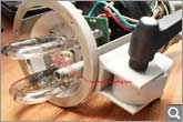
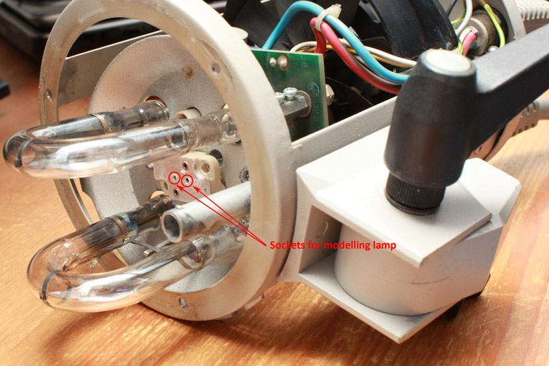
This is where the GX6.35 bulb used on higher-end pack heads plugs in. I tried a handful of bulbs all of which worked on other heads and none of them would light.
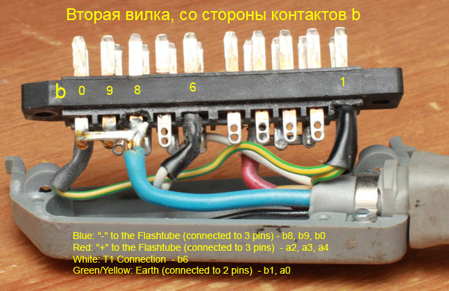
The next step was to open up the plugs to check the wiring. The first one I opened is the secondary plug. This plug's only function is to power the second flashtube.
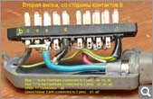
As you can see, the only connections are:
Blue: "-" to the Flashtube (connected to 3 pins)
Red: "+" to the Flashtube (connected to 3 pins)
White: T1 Connection
Green/Yellow: Earth (connected to 2 pins)
This is all that's needed for a "dumb" head - in theory all converting a head to another brand of pack involves is making sure these 4 connections are made.
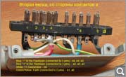
Next up was the primary or "pilot" plug. This plug has the same connections as above for its flashtube, plus all the extra connections which power the fan and modelling lamp.
As well as the flashtube connections you can now see:
Blue (2): Fan 1
Red (2): Fan 2
Black: Modelling Light 1
Yellow: Modelling Light 2
Testing continuity between the two pins for the modelling light and the sockets the lamp plugs into showed that there was continuity for the black wire but not the yellow wire. Time to delve deeper.
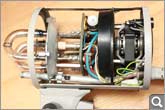
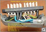
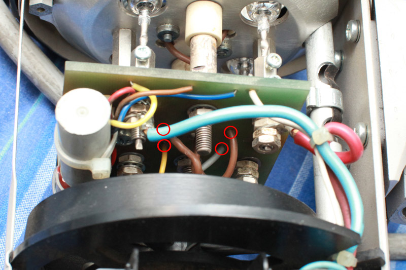
This is the opened up head. In the bottom right you can see all the wires emerging from the flex. The yellow wire goes straight into the pcb. The black wire is routed through the fuse (top right) and the connection continues as a grey wire which also connects to the pcb.
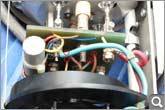
The yellow and grey wires connect to the two brown wires via the pcb which, go straight into the lamp fixture. I was suprised to find out that this is all there is to the wiring for the modelling lamp.
Testing at the point the yellow wires connects to the pcb showed that there was still no continuity with the pin on the plug. There was continuity between both sockets in the lamp fixture and their corresponding wires on the pcb. The conclusion is a break in the yellow wire somewhere along the length of the flex.
Thought I'd share this little series for anyone curious about how these things work.
Personally I'm glad to have gone through this as I've now seen that these heads are actually ruthlessly simple. The flashtubes might not be the modern plug-in type but loosening & re-tightening a couple of screws is all it takes to change one. The myriad of pins on the plug is no longer intimidating as I've seen that the majority of them are empty, and those that aren't correspond excatly with what is detailed here: http://www.lumix.fr/Photo/Other_items/Cable.html
...
I soldered a new wire to replace the one that had the break. Had to run it on the outside of the flex and then wrap the whole thing in electrical tape to secure it which doesn't look pretty, but it took 15 mins, cost nothing and the modelling light works fine. One of these days I may get the flash centre to put a new flex on it as I have zero faith in my soldering skills.


a0 - земля, GND.
a2, a3, a4 - анод импульсной лампы, XE-A.
a6 - пилотная лампа 2, Modelling Light 2
a7 - пилотная лампа 1, Modelling Light 1
a8 - вентилятор 2, Fan 2
b1 - земля, GND.
b6 - поджиг (Trigger), T1 Connection
b7 - вентилятор 1, Fan 1
b8, b9, b0 - катод импульсной лампы, XE-K.
Распайка разъёма (20 штырьков, DIN 41622) ведомой лампы:
a0 - земля, GND.
a2, a3, a4 - анод импульсной лампы, XE-A.
b1 - земля, GND.
b6 - поджиг (Trigger), T1 Connection
b8, b9, b0 - катод импульсной лампы, XE-K.
В следствие постоянных модификаций у конкретного образца оборудования распайка может отличаться. Поэтому всегда следует перепроверять сведения. Тем более, что:
---Hermes писал(а):but definitely don't take my word for it as I a) know nothing about electronics and b) haven't had occasion to open up any of my heads since I first posted this.
Дополнительно: Elinchrom Digital 3000 AS.