Дополнительно по теме: Внешние разъёмы фотовспышек и камер.
TTL Flash Interface connections
http://www.camerasunderwater.co.uk/arti ... /ttl-flash
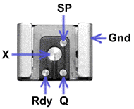
Gnd = Ground, Earth, Mass, Common.
X = X (trigger) contact.
Q = Quench or TTL stop.
Rdy = Ready to fire
SP = Speedlight present (Monitor).
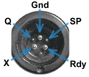
The Nikonos interface (below) is electrically identical.
Nikonos TTL flash interface
Nikonos bulkhead socket. Nikonos camera. Nikonos plug on sync.cable.

Nikon interface connections and signals (analogue)
Rdy (strobe ready to fire): When the strobe asserts a +3 V active high signal to the Rdy contact, a Nikon or Nikonos film camera switches to X-sync speed if a higher speed has been selected. Rdy high also turns-on the viewfinder lightning-bolt symbol. The Nikonos and some other cameras draw a few mA from the Rdy line, the viewfinder LED being powered directly through a resistor. The ready line can therefore be used as a power supply for low-power circuits that can run on 3 V (but the Sea & Sea strobes with Duo connector and the YS60N are a special case, see below).
X (Trigger): The camera shorts the X-contact to ground when the shutter is fired. Electronic SLR cameras use a thyristor for this function, and the X-terminal short-circuit output current from the strobe(s) must be limited to no more than about 1.5 mA to allow the thyristor to de-latch after firing. The strobe input is typically a logic-gate with a pull-up resistor to the logic B+ rail, and the value of the pull-up resistor sets the X-terminal current in the logic-low state. Up to 2 strobes can be connected in parallel, so strobe designers should choose the pull-up resistor so that the X-terminal short-circuit current is no more than about 750 µA (e.g., the pull-up resistor for 5V logic is 6.8 kOhm). Earlier strobes that use 3.3 kOhm pull-up resistors (or less) must be modified for dual-strobe use with electronic cameras.
Q (Quench / TTL stop): In a conventional TTL flash system, the camera integrates the light falling on the film (using a phototransistor and a capacitor), and when the integrated level reaches a threshold determined by the film ISO (ASA) setting, the Quench line is shorted to ground via a transistor. The Quench signal tells the strobe to switch-off the flash-tube current. The camera calibration specification is that for ISO100, an aperture of f/5.6, and constant LV15 (K=1.16) from a light box, the time between X going low and Q going low (txq) is 820 µs. This is slightly shorter than the 'ideal' 977 µs (1/1024 s), to allow the strobe some time to switch off.
Out of ISO range: When the camera ISO setting is too high for accurate TTL flash operation, a Nikon film camera holds the Q line low as a warning signal, and TTL control is unavailable. The Nikonos V holds Q down for ISO 400 or higher. Since Q low with X high is a warning signal, this situation should never be allowed to occur during the normal firing sequence, i.e., after firing the strobe, Q should be returned high before X is returned high. In Nikonos SB-series strobes, and original Ikelite Substrobes, Q low with X high causes the Rdy output to pulse on and off (i.e., it causes the viewfinder ready symbol to flash).
The SP (Monitor) function:
("speedlight present" is probably not what SP stands for, but is a good enough way of remembering what it does).
 If the interface is implemented as Nikon intended, when a TTL capable camera is connected to a TTL capable strobe, a current of around 100 - 250 µA flows along the SP line (camera positive). Since the SP input of a Nikon SB-series strobe is the base of a bipolar transistor, a voltage of 0.6 V - 0.7 V will be seen at the SP terminal of a Nikon strobe when the current is flowing. If the Camera cannot detect a current flowing in the SP line, it will not output a Quench signal. Why this feature was included is not clear. It seems to serve no useful purpose and makes the system less reliable. Independent users of the Nikon interface often disable the SP function by grounding the camera terminal via a resistor. A resistor of value between about 3.3 kOhm - 11 kOhm works well for Nikon film SLR cameras. 3.3 kOhm - 6.8 kOhm works well for the Nikonos V and RS-AF. Drawing a small amount of current from the SP line fools the camera into believing that a TTL strobe is connected.
 Note: The SP connection serves a different function with the later Nikon digital SLR cameras (The dTTL and iTTL systems). The interface protocol has changed completely and, unless an adapter module is used, such cameras will only operate in manual flash mode and SP must be left disconnected when using non-Nikon non-dTTL compatible strobes. Hence the camera information given here applies mainly to the Nikonos, Nikon 35 mm film SLRs, and the Fuji S2 (which uses the ordinary analog Nikon protocol).
 In the Inon Z220, the SP signal from the camera (activated when the shutter is half-pressed) is used to operate the focusing light. Note that the strobe must be in Nikon mode for this functionality, i.e., the magnet must be in the 'N' hole.
 Ikelite overrides the SP function by placing a 3.3 kOhm resistor from SP to ground inside the Nikonos plug of its ICS5 to Nikonos TTL sync cables.. Hence only 4 wires are needed in an Ikelite TTL Nikonos cable.
 The Sea & Sea YS50TTL/N overrides the SP function by placing a 6.8 kOhm resistor from SP to ground inside the strobe. Hence 5 wires are needed in the cable. Sea & Sea YS-Duo series strobes (including the YS90A) and the YS60N will not assert Rdy until SP is asserted. SP in this case is used to determine whether a Nikonos TTL or a Sea & Sea TTL camera is connected, but this deviation from standard practice makes Duo strobes partially incompatible with the Nikonos IVa (The IVa must be switched to the X-sync speed manually). TTL quenching is still possible with SP disconnected, but the ready line always stays low. If you want to activate the Rdy function, connect a 100K resistor from X to SP (but note that the Rdy line voltage obtained is only about 2.1 V). Nikonos Speedlights and true clones feed the SP line to the strobe, and the strobe will not function in TTL mode if SP is left un-connected. In these cases the strobe can be fooled into thinking a TTL camera is present by connecting the strobe SP terminal to a positive supply via a resistor. A resistor in the range 22 kOhm - 47 kOhm from SP to Rdy is usually sufficient.
Suggested interface circuit for TTL converter with Nikonos 5 connector:
A TTL protocol converter needs only two open-collector active low outputs: X and Q. In order to ensure that the maximum variety of strobes will work correctly however, some additional components are needed at the connector interface. An optional ready light can be implemented by connectiong an LED and series resistor between Rdy and Ground. A 100K resistor between X and SP injects sufficient current into the SP terminal to activate the Rdy line of the Sea & Sea YS60N and YS strobes with a Duo connector, and to turn on the focusing light of the Inon Z220. Nikonos SB-series strobes cannot be made to work in TTL mode by this means however, and so require a resistor (22K - 47K) from Rdy to SP.

Maximally compatible Nikonos interface (view looking into socket).
This circuit has been tested in TTL mode with:
Sea & Sea YS50TTL/N (GTO),
YS60N, YS90A,
Inon Z220,
Nikonos SB105 (GTO),
Ikelite DS50 (IGBT) s/n<70000,
Ikelite DS125 (IGBT) s/n>5000.
Note that this interface does not guarantee that a particular strobe will always work with a TTL converter. An additional mandatory requirement is that the strobe should be able to recover and be ready to fire within the preflash to main flash interval of the flash control system. Strobes with a GTO series control element can recover in about 100ms, and so will often work with long-interval preflash systems such as Olympus (125ms), but not with short-interval systems such as Canon eTTL (70ms). Strobes with an IGBT series control element can recover in about 30ms, and should work with all presently available full-intensity preflash systems. It follows; that since the Nikonos SB series speedlights all use GTO circuitry, there is no point in putting the 33 kOhm resistor from SP to Rdy if the TTL control system requires a short pre-to-main flash interval (i.e., if legacy SB speedlights and clones cannot be used, there is no point in making provision for them).
If there is room in the housing, a normally closed (NC) switch can be arranged to keep SP shorted to ground until the shutter release is half-pressed. Alternatively, a normally open (NO) switch can be used to keep SP disconnected until the shutter is half-pressed. Either of these measures will cause the Inon Z220 focusing light to be activated with the shutter control. One disadvantage of such a provision however, is that it will cause the Rdy line from a Nikonos SB strobe to pulse on and off until the shutter is half pressed. Consequently, if a ready LED is included at the interface, it is advisable to provide a switch or control enabling the user to opt for SP inactivation only if an Inon Z220 is used. Alternatively, a more complicated circuit can be used to suppress the ready LED when the SP output is inactive (as is done in the Nikonos V).
Ikelite TTL Interface
The original Ikelite TTL flash interface is a subset of the Nikon interface with the SP function omitted.


ICS5 bulkhead connector (strobe or housing). ICS5 plug on sync cable
T- and B+6.5V
On an early Ikelite TTL Substrobe (pre DS-series), the pin labeled T- is provided for compatibility with non-TTL cables. Such cables fire the strobe by shorting between X and T-, whereas a TTL cable fires the strobe by shorting between X and ground. For historical reasons (Ikelite solid-state triggering (SST) system), T- is not grounded, but connects via resistor to the gate of the tube-trigger thyristor. This means that the strobe can also be triggered by applying a current-limited (~1 mA) positive pulse between T- and ground. On an Ikelite film SLR housing, the T- pin is not connected. The T- receptacles are likewise not connected (N/C) in a #4103 Ikelite to Ikelite TTL cable or in a #4104.6 Ikelite to Nikonos TTL cable. In the Ikelite DS-series interface, the T- function has been removed and replaced with a power-output connection (B+ 6.5 V) for the strobe-powered 4100.5 slave unit, the 4100.6 EV controller, and hot-shoe protocol conversion modules in digital camera housings. Hence Ikelite digital housings with TTL converters (e.g., Olympus TTL housings, Canon eTTL housings) require a special 5-core sync cord #4103.51 (marked with a blue band), the extra wire being for the power supply connection.
Note: Given that the T- function has disappeared, old 2-core manual Nikonos leads must not be used with DS-series Substrobes.
SP: In an Ikelite film-SLR housing, the SP function is disabled by connecting SP to ground via an 11 k? resistor (it varies) inside the hot-shoe connector.
In non-Ikelite SLR housings, the SP connection us usually brought out to a Nikonos bulkhead connector for compatibility with Nikon SB-series speedlights and clones.
Ikelite wire colour codes
Black = Gnd. White = X-contact, Green = Quench, Red = Ready, Grey = T- or B+ 6.5 V.
Sea & Sea Duo Flash Interface


This is a non-standard Nikonos interface, its behaviour being dictated by the additional requirements of the Motormarine II system:
The Rdy line serves as the S (start integration) signal for the MM2 interface if SP is not asserted. Hence the strobe with a Nikonos V connector cannot switch a Nikonos IVa camera to X-sync mode (Nik III and IVa cameras do not connect SP). In the MM2 protocol, the Q line also serves to light the TTL OK LED in the camera viewfinder. Hence, if SP is not asserted, the Q line is only pulled-up when X is pulled low; or, after firing, when the green TTL OK light on the strobe is lit. In the MM2 protocol, the X line is only pulled up when the red Rdy light on the strobe is lit. Voltage on the X line is sensed to light the red Rdy LED in the camera viewfinder. If a 100 k? resistor is connected from X to SP, the Rdy line becomes active, the TTL OK function via the Q line is disabled, and the Q line is pulled up continuously rather than only when X is low. The Rdy line output voltage is sub-standard however (~2.1 V), and so protocol conversion modules powered from the Rdy line must be of very low voltage design if Sea & Sea compatibility is required.Sea & Sea Motormarine II/EX (and SX-1000) Flash Interface

X: The flash ready function is provided by a positive voltage (+5.6 V nominal) appearing on the X terminal (i.e. the X-terminal is at 0V when the flash is not ready).
S: Integration of light falling on the film is initiated when the flash unit places +3 V to +4 V on the S (start integration) terminal.
This +3 V serves as the power supply for a 2903 comparator in the camera (see circuit below). Phototransistor (PT) current charges a capacitor, and when the capacitor voltage exceeds the ISO (Film DX coded) set-point, the comparator shorts the Q-line to ground. The leading edge of the S pulse momentarily turns on a transistor (Q4) which discharges the integration capacitor to initialise the system.
Q: Two-way communication occurs on the Q line. The pull-up resistor for the Q input of the strobe is only powered while the X line is low. When X goes low, Q is pulled up (goes high). The camera then pulls the Q line low when integration is complete. The flash unit asserts a high on the Q line (via a resistor) for a few seconds if quenching is successful, to light the TTL OK LED in the camera viewfinder.
 indicates ground.

D W Knight
© Cameras Underwater 2004.

