Hi to all,
I am triyng to add to Metz 60CT1 manual control and following power reduction:
Full , 1/2, 1/4, 1/8, 1/16, 1/32, 1/64
On 45CT series you need to replace lightsensor with this resistors: 2,2M, 56K, 22K, 15K , 10K , 5K6, 3K9
https://impulsite.ru/ctlg/metz/45ct1/me ... t1.pdf.zip
I am not too good in electronics, but I have tried whit this resistors on my 60CT1 but it fires allways full power
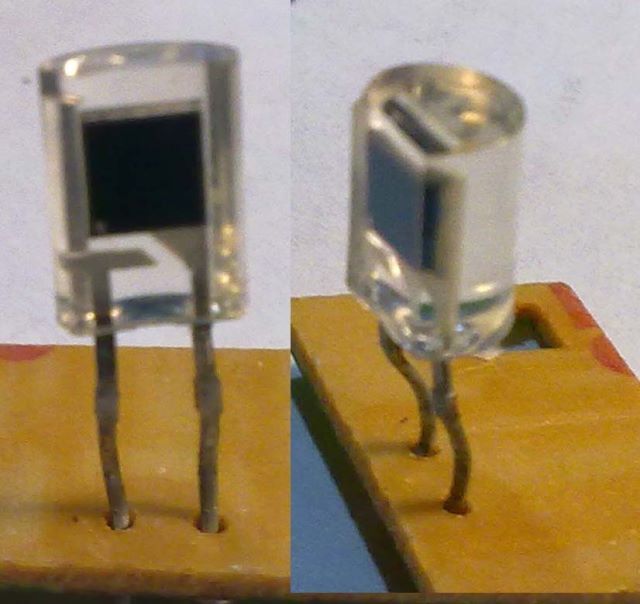
This is the light sensor, meaby I need some other components? Anyone know where to get metz schematics :-)
Привет!
--
Привет всем,
Я пытаюсь добавить в Metz 60CT1 ручное управление мощности: полная , 1/2, 1/4, 1/8, 1/16, 1/32, 1/64 мощность
На серии 45CT требуется заменить фотодатчик резисторами: 2,2 М, 56к, 22к, 15к , 10к , 5к6, 3к9
https://impulsite.ru/ctlg/metz/45ct1/me ... t1.pdf.zip
Я не слишком силён в электронике, но я попробовал в моём 60CT1 заменить фотодатчик резисторами, вспышка срабатывает всегда на полную мощность.
Это фотодатчик, может быть мне нужны какие-то другие компоненты?
Кто-нибудь знает, где взять схемы Metz?
Привет!


