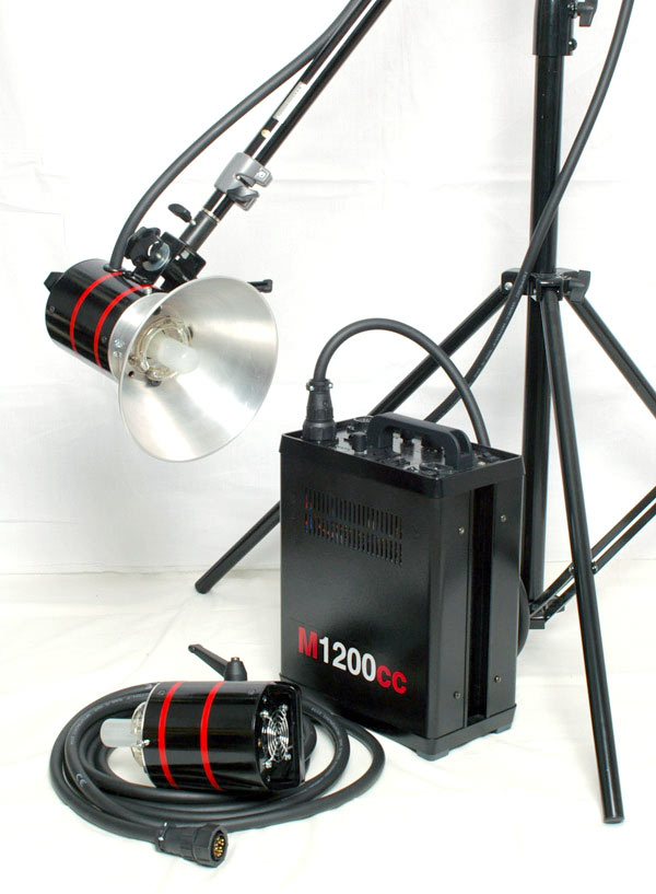
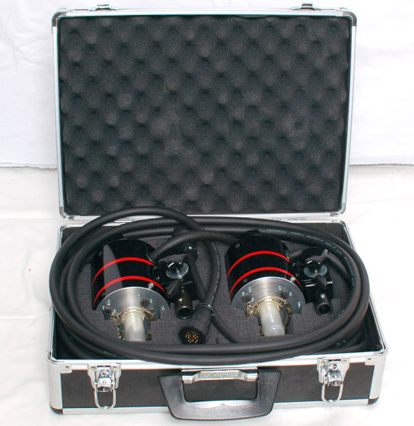
One of my 1200Ws generators.
This flash generator (or Power pack) was designed in winter 2005.
Most images enlarge when clicked.
Some short points:
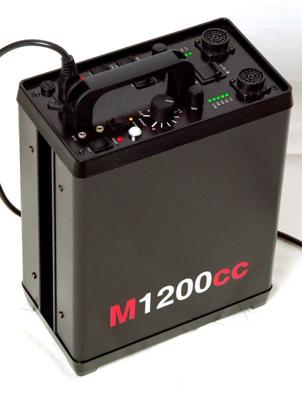
The generator is housed in a Schroff Compac general-purpose cabinet (3HU/42TU), that I found second-hand. This cabinet is absolutely perfect for the present application, and has many options for secure mounting of PCBs and other components inside.
Of course, the generator is divided into a high voltage part and a low voltage part that commmunicate using optocouplers. The low voltage part operates from a 5V supply, and is based on a PIC16F874 microcontroller, which takes care of all control and user interface tasks.
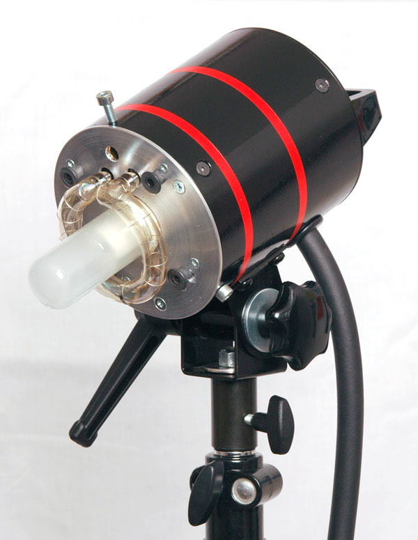
In this generator, I took advantage of the fact that my energy reservoir consists of many small capacitors. By arranging them in banks that can be individually connected to the flash head, it is possible to set the flash energy by changing the number of connected capacitors, instead of the voltage. This solution is intended to give consistent colour, and shorter flash durations.
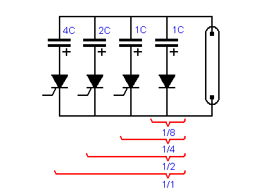
As this method offers only whole f-stop changes, there is also a stepless master energy control, which allows to reduce the total energy by as much as -1.0 f-stop by controlling the voltage. This translates to a voltage range of 71-100%, which does not significantly affect the colour (see the 'performance' section below.).
The charging circuit operates using two different time constants - one fast for quick recycling, and one slow for maintaing a stable charge (and for slow charging on power-up).
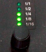
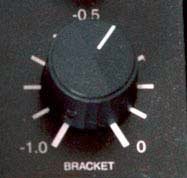
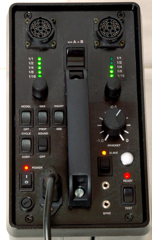
For both channels, the flash energy can be set from full to 1/16. This is adjusted using rotary selector knobs, and the current setting is shown on a LED bargraph display. The lit LEDs correspond directly to the thyristors that are turned on when the generator is fired. On the right hand side, there is a master bracket dial, which allows for fine adjustment of the overall light intensity. This dial has a scale with 1/10 f-stop markings. The voltage is internally calibrated, using three precision trimmers, to a +-1V accuracy for the max-, min- and midpoint of this scale. An auto-dumping feature kicks in when the bracket dial is turned down. The excess charge is then removed using a bleeder resistor. This way, there is no need for firing the generator to get the correct energy level.
Between the two flash head connectors, there is a big rocker switch which is used to choose between using the two channels separately (two heads), or to add the energy of channel B to the flash head connected to channel A (using one head). In this mode, flash energies up to 1200Ws can be sent to one head.
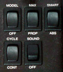
A set of five switches allow for setting some preferences. The switch marked MODEL/OFF is used to turn the modelling light on or off. MAX/PROP selects whether to turn on both lamps at full power, or to have them dimmed proportionally to the energy settings of the two channels. SMART/ABS offers a function where the modelling lights are proportional to the difference between the two channels, but the channel that has the highest energy will have its modelling bulb fully on - e.g. if the setting is 1/8 for A and 1/16 for B, bulb A will be at 250W and bulb B at 62W. CYCLE/CONT selects whether the modelling light should be continuously on, or turned off when recycling. Finally, SOUND/OFF offers a 'beep' signal to indicate when the generator is ready to fire.

There is also a slave photocell option. When turned on, the generator will be triggered by the light from other flashes going off. The white dome is actually an opalised glass cover from an old signal lamp.
If the generator is turned on whilst holding the TEST button pressed, the capacitor forming mode is activated. The voltage over the main reservoir capacitors is then brought up very slowly to its maximum value, where it should stay for some time. All other functions are disabled in this mode. This exercise is for reducing the risk of capacitor failure if the generator has been unused for a long time.
Also when the generator is turned on normally, it will charge slowly for 10 seconds before starting normal operation, for the same reason.
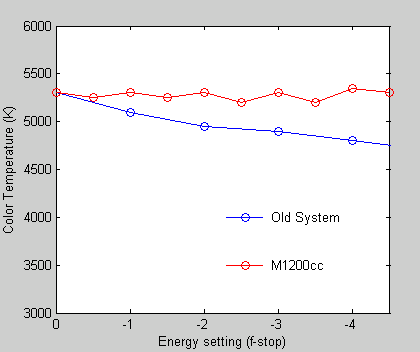
This graph shows the colour temperature (red line), as measured for the M1200cc flash system, versus the energy setting. It is clear that the temperature remains roughly independent of the energy setting. The slight drop seen for every half f-stop is due to the voltage control used to set fractional f-stops.
For comparison, the corresponding measurements are shown for an older flash project (blue line), where the energy is set using voltage regulation only. In this case, the colour temperature displays a continuous decline when the energy is dialed down, with a non-negligible difference in colour when high and low settings are compared.
This experiment was a simple test, but it shows that the colour consistency of the new system is more than adequate for an amateur photograher like me.
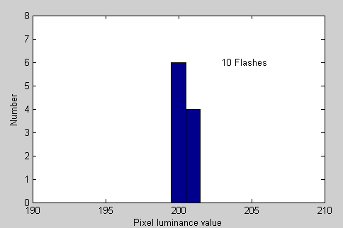
This histogram shows the distribution in measured pixel luminance from the ten shots. It can be seen from this graph that the variation is not more than ± 1 in pixel luminance. This translates to a stability better than 1/100 f-stop. Once again - for an amateur photographer, this is quite satisfactory.
Warning! Flash circuits are very, very dangerous! Never attempt a project similar to this one if you do not have the right experience and equipment. If you just want to get a flash unit at low cost, there are plenty on the second-hand market.
(c) Marcus Gunnarsson 2005-2006